Introduction
The page heading editor in pre-2019 releases of SuperBeam, ProSteel and EuroBeam dates back to the introduction of ProSteel 1 in 1993. It handled the heading as an 8x4 matrix of cells, each of which could optionally contain text (in one of four user-selected fonts) and/or be surrounded by lines on one or more sides.
The current heading designer, has been available since EuroBeam 3.19, SuperBeam 3.19 and ProSteel 3.19.
The heading area starts as a blank canvas on which you can place one or more of the following, positioned as you wish:
- Text: you enter the text and define its position, font and alignment
- Line: you define the line ends, line thickness and colour
- Rectangle: you define the top left, width, height, fill colour, and optionally border colour, border thickness and border radius.
- Circle: you define the centre, radius, fill colour and and optionally border colour and thickness.
- Ellipse: you define the centre, x and y radii, fill colour and optionally border colour and thickness.
- Polygon: you define the x and y coordinates of the vertices, fill colour and optionally border colour and thickness. For regular polygons, a wizard calculates the apex positions for you.
- Image: you select an image that you have on your PC (typically a logo) and define the top left corner, height. The image width is derived from the height, maintaining the original image proportions.
- Page border: This is not technically part of the heading, but has been added here following user requests. You define the border indent from each side, thickness, colour and optionally the border radius.
Units
IMPORTANT: : In the new designer you enter positions, dimensions and thicknesses in 'units', where one unit = heading width/1000. Thus 0 is the left edge of the heading, 1000 the right edge. For A4 paper one unit is a fraction less than 0.2mm. Example: a circle with a centre at 950,50 and a radius of 50 will just touch the top and right edges of the heading, whatever the printer.
This may seems a bit arcane: whole digit percentages would have been much easier to explain but would give a resolution of about 2mm, too coarse where different elements have to be aligned accurately.
Using the heading designer
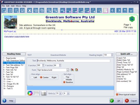
The screen
The heading designer window is divided into the following areas:
- Menu: Split into File (open, save etc), Edit (cut, copy, paste, reorder), Add (text etc), Move, Help.
- Toolbar: provides a quick way of selecting the most used menu options
- Preview pane: shows what your heading will look like.
- Item list: This lists the various items (text, lines etc) making up the heading. At print time items are rendered in the order in which they appear in this list, so if two overlap the second will be printed over the first.
- Properties pane: This shows the properties (e.g. position, colour, border thickness) for the currently selected item. The contents reflect the currently selected item.
- Quick add pane: Used for text items incorporating % replaceable parameters (these are unchanged from earlier releases).
- Configuration options bar: Change the colour picker style, x and y grid increments.
Menu options
The options marked with an asterisk have a corresponding toolbar button.
- File: New, Open*, Save*, Save As*, Print*, Exit are all self explanatory.
- Edit: Cut*, Copy*, Paste* perform these operations on the selected item. Note that your cannot copy or paste a page border; each heading can have no more than one border.
- Add: Text*, Line*, Rectangle*, Circle*, Ellipse*, Polygon*, Image*, Page Border*. See below for more details.
- Move: Left*, Right*, Up*, Down*. The selected item is moved by the distance shown in the selector on the configuration options bar (x: left/right; y: up/down).
- Help: Online help (this page), About
Adding items to your heading
To quickly initialise the position of the new item, click on the preview pane as outlined below before selecting the appropriate 'Add' option from the menu or toolbar.
- Text: Clicking on the preview pane sets the anchor point. Select/press Add Text and in the fields provided enter the text, select the required font and the text position (horizontally and vertically) with respect to the anchor point. If the text position needs adjusting, change the x or y position field or use the appropriate Move button. To change the font, press the button at the end of the font line and select the font you want. The two buttons at the end of this line save the current font and change the current font to the previously saved one.
- Line: For speed, click twice on the preview, once for each end (hold the shift key down while clicking for the second time to get a horizontal or vertical line). Select Add Line and select the line thickness and colour, adjusting the end coordinates if necessary.
- Rectangle: For speed, click twice on the preview, marking the top left and bottom right corners. Select Add Rectangle and select the fill colour, adjusting the corner coordinates if necessary. Optionally, set the border thickness (0=no border), border colour and border radius (0=square corners).
- Circle: For speed, click twice on the preview, marking the centre, then a point on the circle. Select Add Circle and select the fill colour, adjusting the centre coordinates and radius if necessary. Optionally, set the border thickness (0=no border) and colour.
- Ellipse: For speed, click twice on the preview, marking the top left and bottom right corners or the bounding rectangle. Select Add Ellipse and select the fill colour, adjusting the centre coordinates and x or y radii if necessary. Optionally, set the border thickness (0=no border) and colour.
- Polygon: Select Add Polygon. A text field is provided
where you can define the polygon as a series of x,y coordinates (in units as above),
comma separated. These numbers can have one decimal place for greater precision. For
example 50,50,150,50,150,150,50,150 would define a square with sides 100 units long -
note that a closing line is automatically drawn from the last point to the first.
For regular polygons, press the button at the end of the line to activate the Polygon Wizard. Enter the number of points, centre x/y, the radius (from centre to apexes) and the angle measured from the centre to the first apex from vertical. Thus to get the square above, you'd enter centre 100,100 radius 70.7, start angle 45. If you entered a start angle of 0, you'd get a diamond orientated square. Select the fill colour and optionally set the border thickness (0=no border) and colour. - Page border: Select Add Border and enter the insets of the border on each side. Set the border thickness, border colour and border radius (0=square corners).